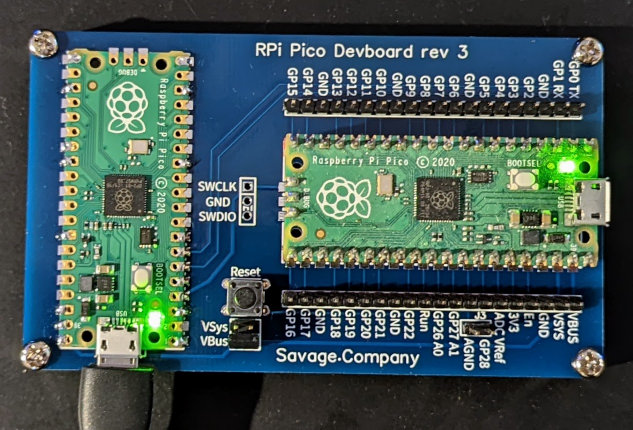
RaspberryPi Pico Dev Board
Updated to support the new debugprobe with support for the RP2350.
The RPi Pico is a great, low-cost, powerful ARM-based development platform. This dev board enhances the platform with a carrier board with the following:
- A debug host (using debugprobe) for on-chip debugging of code
- A serial interface (again via debugprobe)
- The missing reset button!
- Breakout of all pins from the pico
- Development board powered by either the VSys or VBus sources
Compatible with all Pico variants
- Pico
- Pico-H
- Pico-W
Schematic and PCB Layout are available at OSHWLab.
Getting Started
The PCB has a few configuration options. The development and debug host pico can be soldered directly onto the board (using castellated pads).
I prefer to solder the debug host pico directly to the board with the development pico mounted to the board via headers.
Preparing the hardware
Required Tools
Tools you are going to need
- Soldering Iron
Required Components
General components required for all mounting approaches
| Part | Count | |
|---|---|---|
 |
RPi Pico Devboard | 1 |
 |
Pico debug host (cannot use a pico-h) | 1 |
 |
20x1 Male Headers | 2 |
 |
2x2 Male & 2x1 Male Headers | 1 |
 |
Micro pushbutton (reset) | 1 |
 |
Jumper (to enable VBus/Vsys & AGnd) | 1-2 |
With the development board mounted using headers.
| Part | Count | |
|---|---|---|
 |
20x1 Female Headers | 2 |
 |
3x1 Male & Female Headers (debug port) | 1 |
If you wish to mount the debug host using headers, another pair of 20x1 Female headers is required.
Optional Components
These components are optional but recommended to raise the board off the table.
| Part | Count | |
|---|---|---|
 |
M3 Screws | 4 |
 |
M3 Standoffs | 4 |
Building the Board
-
Solder the Pico debug host to the board. First, line up the Pico and solder one corner. Ensure the Pico is still aligned and solder the opposing corner.
All pads marked with a red dot should be soldered (the rest are optional)
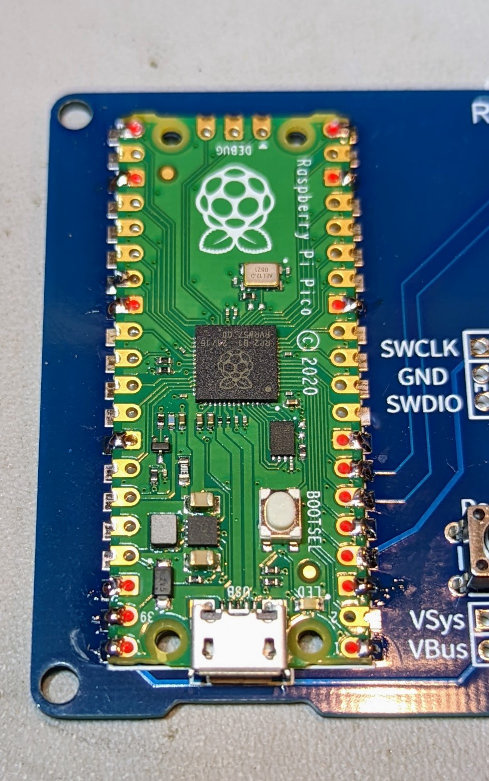
Tip! The pads with squared-off edges are Ground pads. As the ground plane on the back of the dev board is large, it acts as a heat sink.
Hold your soldering iron next to the pad for a few seconds to add heat to the dev board before adding solder to make this easier. -
Solder the reset button to the board.

-
Solder the male headers to the board.

- Solder the female headers to the board. Before soldering, use a pico to line the headers up to ensure they are aligned.
-
Add headers to a pico

-
Solder it in place

-
-
Add the jumper to enable VBus or VSys to power the dev pico from the debug pico. VBus is recommended to take power straight from the USB bus.

Preparing the software
You will need:
-
Pico SDK installed
-
A working IDE for debugging
Follow the instructions for setting up PicoProbe and installing the firmware in Chapter 10. Using other Integrated Development Environments of the Getting Started with Pico user guide.
-
Pico Probe and OpenOCD
Follow the instructions for setting up PicoProbe and installing the firmware in Appendix A: Using Picoprobe of the Getting Started with Pico user guide.
If you are happy to use Visual Studio code, you should now have a working development environment with debug support. If you prefer CLion (I do), follow on to the next section.
Configuration of Open OCD in CLion
This section assumes you have a working build in CLion after following the Getting Started with Pico user guide.
The user guide skips the final step of hooking into OpenOCD via GDB in CLion, allowing you to hit run and debug directly in the IDE, set breakpoints, and step through your code.
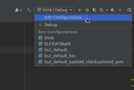
-
Open the edit configs window
-
Add an embedded GDB Server
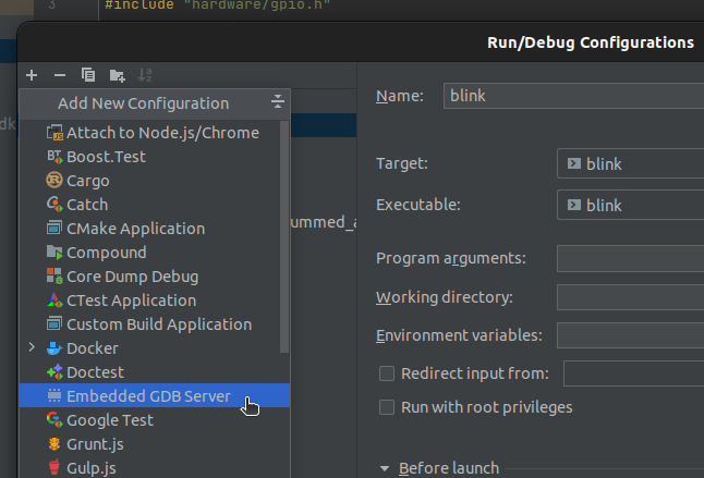
-
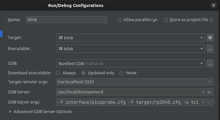
Select your target and executable and use the following settings:
Setting Value ‘target remote’ args tcp:localhost:3333GDB Server1 /usr/local/bin/openocdGDB Server args -f interface/cmsis-dap.cfg -c "adapter speed 5000" -f target/rp2040.cfg -s tcl1 Location where OpenOCD binary was installed
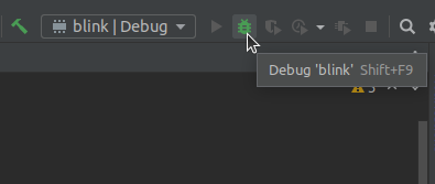
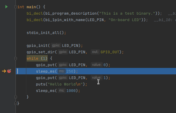
-
Hit Debug and set a breakpoint!
Gotchas
Open OCD unable to access Debug Probe on Linux
The port used to access the debug probe is r/w to root only. A UDev rule is required to change the port’s ownership.
Place the following into the file: /etc/udev/rules.d/60-openocd.rules
# Raspberry Pi Picoprobe
ATTRS{idVendor}=="2e8a", ATTRS{idProduct}=="0004", MODE="660", GROUP="plugdev", TAG+="uaccess"
# Raspberry PI Debugprob (CMSIS-DAP)
SUBSYSTEM=="usb", ATTRS{idVendor}=="2e8a", ATTRS{idProduct}=="000c", MODE="0660", GROUP="plugdev", TAG+="uaccess"
Reload the rules with: sudo udevadm control --reload-rules
Next, reconnect the dev board to update permissions.
And finally, add your user to the plugdev group with:
Assuming your distribution uses sudo:
sudo usermod -aG plugdev $USER
You will need to re-login for this change to take effect.